
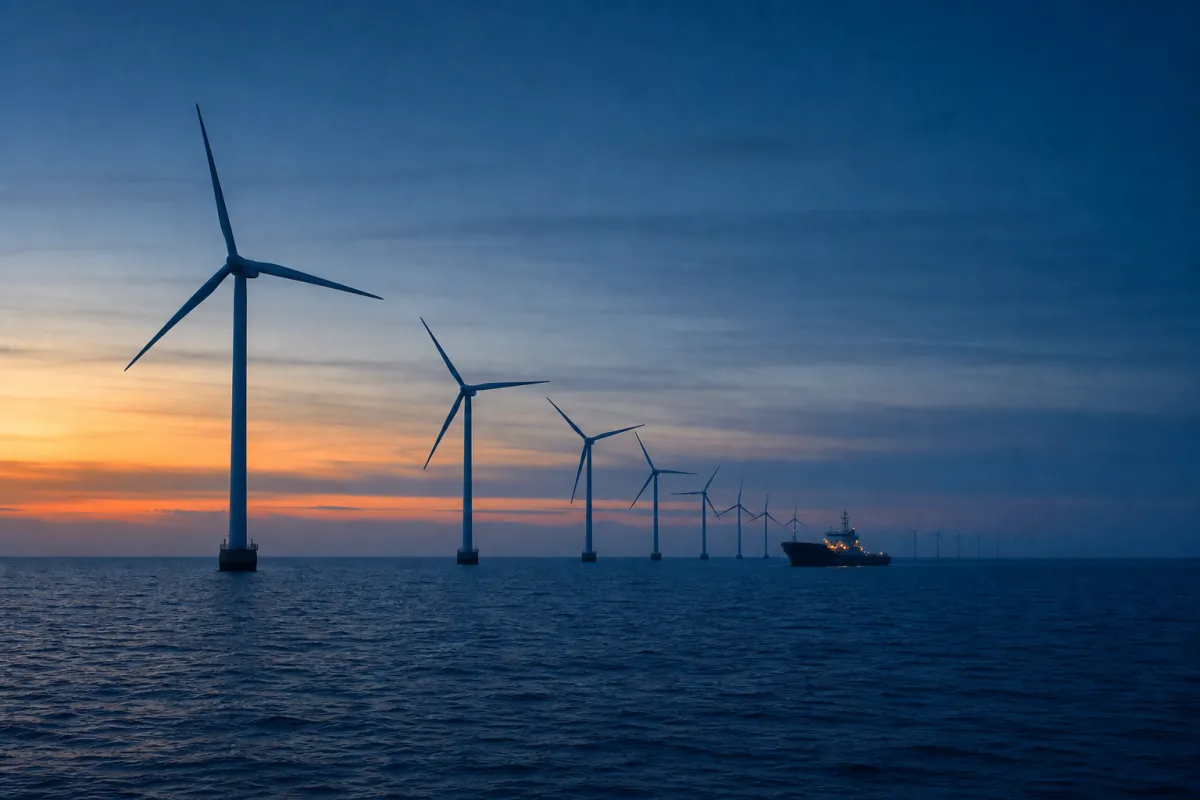
600-tonne nacelles, 115-metre blades — installed from a deck that will not hold still.
Heave Compensation for Offshore Wind
Wind Turbine Installation Challenges
Offshore wind turbines are installed using jack-up vessels, heavy-lift crane vessels, or semi-submersible platforms. As turbine sizes grow beyond 15 MW — with nacelles weighing over 600 tonnes and blades exceeding 115 m — the lifting operations become increasingly sensitive to wave-induced motions.
Practical application: For practical application of this topic, see POLARIS crane shock absorber and custom heavy lifting equipment.
Key installation phases where heave compensation matters:
- Monopile/jacket placement — lowering a 1000+ tonne foundation through the splash zone onto the seabed
- Transition piece installation — grouting or bolting the TP onto the monopile requires precise vertical positioning
- Tower section lifts — stacking tower sections at height amplifies vessel motions
- Nacelle and blade installation — the highest lifts with the tightest tolerances
Traditional jack-up vessels eliminate heave by standing on the seabed, but they are slow to reposition and limited by water depth. Floating installation vessels offer faster cycle times but must manage wave-induced motions during every lift.
| Installation phase | The lift | Motion challenge |
|---|---|---|
| Monopile / jacket | 1 000+ t | Foundation through the splash zone onto the seabed |
| Transition piece | Grouted or bolted onto the monopile | Precise vertical positioning |
| Tower sections | Stacked at height | Height amplifies vessel motion |
| Nacelle & blades | 600+ t nacelles · 115+ m blades | The highest lifts, the tightest tolerances |
Motion Compensation Solutions for Wind
Several motion compensation approaches are used in offshore wind installation:
- Active Heave Compensation (AHC) — crane winches with real-time motion sensing and hydraulic/electric drive. Used on major crane vessels for heavy lifts. Achieves >95% compensation but requires significant power and control complexity.
- Passive Heave Compensation (PHC) — gas-spring systems that absorb heave motion without external power. Lower cost and simpler operation. Suitable for foundation and subsea component handling.
- Motion-compensated pile grippers — specialised frames that hold monopiles or jackets steady while the vessel heaves. Used by dedicated installation vessels.
- Shock absorbers — protect against impact loads during pile run or sudden load transfer events.
For monopile and transition piece installation, a passive compensator like RIGEL or an adaptive system like ANTARES provides a cost-effective way to extend the weather window without the complexity of full AHC.
For monopile and transition-piece work, RIGEL or the adaptive ANTARES widen the weather window without full AHC complexity; POLARIS covers the pile-run shock case.
Market Outlook
The offshore wind market is growing rapidly. Europe plans to install 300 GW of offshore wind capacity by 2050, and Asia-Pacific markets (China, Japan, South Korea, Taiwan) are scaling fast. Turbine sizes are increasing from 12 MW to 20+ MW, driving demand for larger cranes and better motion compensation.
This growth creates opportunities for heave compensation equipment in several areas: floating installation vessels that need crane compensation, crew transfer vessels using motion-compensated gangways, and cable-lay operations requiring constant tension systems. As the industry moves into deeper water with floating foundations (semi-sub, spar, TLP), the need for effective heave compensation during tow-out and hook-up operations will increase further.
Heave compensation for offshore wind — frequently asked
Why does wind installation need heave compensation?
Which lifts are the hardest?
Jack-up or floating installation vessel?
What compensation approaches are used?
And as the industry goes floating?
Related on Norwegian Dynamics
- Passive Heave Compensation Basics — Equations, derivation and the efficiency calculator.
- Active Heave Compensation — Inline AHC, MRU input, hydraulic actuation and where AHC fits.
- Splash Zone Crossing — The worst phase of any subsea lift.
Working on a lift that needs this?
Foundation install, monopile setting and TP mating each have a different DAF profile. Tell us the campaign and we'll come back with a compensator selection.