Splash Zone Crossing
The splash zone is where a subsea lift passes through the waves at the surface. What slamming, buoyancy, drag and added mass do to the line there, how slack slings turn into snap loads, and what a passive heave compensator did for a 35 t cover.
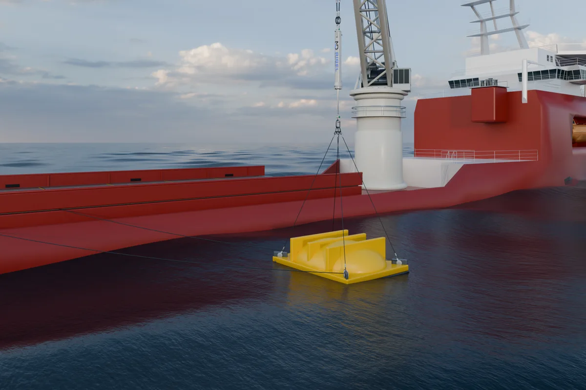
- Four effects act there: slamming as the water hits the object, buoyancy as more of it goes under, drag as it moves through the water, and added mass as the water starts to move with it.
- If the upward forces outweigh the object, the slings go slack and then snap taut. DNV-RP-N103 requires the upward hydrodynamic force to stay at or below 90 % of the object’s minimum weight in water.
- In our study of a 35 t GRP cover at Hs 1.8 m, a RIGEL 75 t / 4.5 m cut the peak line load from 1,846 kN to 655 kN and removed every slack-sling event; the stroke margin was the limit.
A continuous crossing of the splash zone takes only a minute or two, longer if the lift holds for flooding or venting, yet it often sets the sea state the whole lift can be made in. The loads change fastest there, and a light, large-area payload can go slack on its slings as it enters the water.
What the splash zone is
The splash zone is the region around the waterline where a load is partly in air and partly in water. Its height is not a fixed number of metres: it follows the wave crests and troughs and the motion of the crane tip, so it grows with the sea state and with the vessel’s response. An object crosses it on the way down and, if it is recovered, again on the way up.
Four effects that change the line load
- Slamming. Water hits the object’s underside and horizontal surfaces as it enters. The force grows with the square of the impact velocity, F_{\text{slam}} = \tfrac{1}{2} \rho\, C_s A_s v_s^2, where C_s is the slamming coefficient (at least 3 for smooth circular cylinders and 5 otherwise, in the simplified method) and A_s the area that hits the water. It is short and sharp, and often what sets the structural check on the payload and rigging.
- Drag. The water resists the object’s motion through it. The force grows with the square of the relative velocity, F_D = \tfrac{1}{2} \rho\, C_D A_p v_r^2, where A_p is the area seen from below; on a large, flat payload it can exceed the weight in water.
- Varying buoyancy. As more of the object goes under, buoyancy takes part of its weight off the line, and every passing wave changes the submerged volume and with it the line load, F_\rho = \rho\, \delta V g.
- Added mass. The water around the object has to accelerate with it, so its inertia grows as it goes under. With the crane tip and the waves moving, that adds a force proportional to the relative acceleration.
How much buoyancy matters depends on the payload. A dense steel structure keeps most of its weight in water; a light-for-volume object, such as a GRP cover or a module with large tanks, loses a large share of it (about half for solid GRP), while its large area catches the waves (Figure 1). Our subsea lifts article works through drag and added mass with numbers.
Slack slings and snap loads
If the buoyancy and the upward wave forces outweigh the object, the slings go slack. When they come taut again a moment later, the line takes a snap load, often far above the static weight. The simplified method in DNV-RP-N103 combines the four effects into one characteristic hydrodynamic force, F_{\text{hyd}}, and avoids slack slings with a criterion on it:
and where slack slings cannot be ruled out, it gives the snap load from the snap velocity, the stiffness of the hoisting system and the object’s mass with its added mass:
What a heave compensator changes
In line between the hook and the slings, a passive heave compensator makes the hoisting system soft. Its gas spring takes up the crane-tip motion as stroke instead of passing it into the slings, which removes the crane’s share of the object’s motion relative to the water; the water’s own motion remains. The drag and the added-mass force fall, and the lower stiffness K cuts the snap load in the formula above. Sized for the case, it keeps the slings in tension.
Three limits come with it. The compensator must not run out of stroke during the crossing, or the peak loads come back. The object’s weight on the line falls as it goes under, which moves the compensator’s equilibrium, so the stroke available is checked for every stage of the crossing. And a soft system has a long natural period: it isolates the load only from waves well shorter than that period and amplifies motion near it, so the lift model checks the tuning against the wave periods of the operation.
An adaptive passive unit such as ANTARES can switch to a stiffer, better-damped setting for the crossing, so the change in weight and the wave loads use less of its stroke, and soften again below it.
Case: a 35 t GRP cover at Hs 1.8 m
In our CONSTELLATION study CS-2026-004, a 35 t glass-reinforced-plastic protection cover is lowered from a construction vessel through the surface at Hs 1.8 m and Tp 7.5 s. The cover is the awkward class of payload: a large, thin shell that is light for its size, so the waves can lift it on entry. The same payload, sea state, rigging and eight wave realisations were run with rigid rigging and with a RIGEL 75 t / 4.5 m.
| Worst of eight realisations | Rigid rigging | With RIGEL |
|---|---|---|
| Peak line load, against the RIGEL unit’s 736 kN SWL | 1,846 kN (2.5×) | 655 kN (89 %) |
| Payload DAF, against our 2.0 screen | 5.38 | 1.91 |
| Slack-sling events in one run | 11 | 0 |
| Snap-load ratio, against the 0.90 slack-sling limit | 1.00 | 0.36 |
| Stroke used at the governing (retract) end, against our 90 % margin | no compensator | 98.4 % |
Across the eight runs the DAF ranged from 3.41 to 5.38 with rigid rigging and from 1.15 to 1.91 with RIGEL, and the stroke used at the governing end from 83 to 98 %. The snap-load ratio is the drop in line tension below the weight in water, as a share of that weight: at 1.00 the slings go slack, and its 0.90 limit is the DNV-RP-N103 slack-sling criterion applied to the simulated tensions. The DAF and stroke screens are our references for this study, not DNV limits.
The compensated runs passed all four response screens in every realisation. The stroke was the limit: four of the eight used more than 90 % of the stroke towards the governing (retract) end, up to 98.4 %, without touching the end stop, so the tuning would be reviewed before a real lift. At Hs 2.0 m no tested tuning cleared the four screens. Read the GRP cover study →
Planning the crossing
- Screen the sea states. Run the crossing over the wave heights, periods and headings of the operation, with the vessel’s motion at the crane tip. The result is an operating envelope; a weather window needs the forecast to stay inside it for the whole operation.
- Choose the crossing speed. Lowering faster shortens the time in the zone but raises the impact velocity and the slamming. DNV-RP-N103’s simplified method takes a hook speed of typically 0.5 m/s; our case lowered at 0.16 m/s.
- Check both ends of the tension. The minimum tension decides whether the slings go slack; the peak load decides whether the crane, wire and rigging hold. One does not replace the other.
- Confirm it in the time domain. A time-domain model of the waves, the vessel, the crane and rigging, the object’s hydrodynamics and the compensator gives the tensions, motions and stroke for the final check. CONSTELLATION runs it with and without the compensator.
Sources and assumptions
- Slamming, drag, varying buoyancy, the slack-sling criterion and the snap load follow the simplified method of DNV-RP-N103, formerly DNV-RP-H103.
- The case is our CONSTELLATION study CS-2026-004 (Revision C, 5 August 2026): a 35 t GRP cover, RIGEL 75 t / 4.5 m, Hs 1.8 m, Tp 7.5 s (JONSWAP), eight realisations of 120 s; each figure in the table is the worst value of its metric. The 736 kN SWL is the rating of the RIGEL 75 t unit, and the line load is measured in the four-leg sling group above the cover. The cover, a 15 × 12 × 3 m shell, displaces 10.73 m³ and keeps about 69 % of its weight in water. It is a screening study, not a certified analysis.
- Figure 1 is illustrative: steel at 7.85 t/m³ and solid GRP at about 1.9 t/m³, with the wave-driven force as stated in its caption.
Frequently asked questions
What is the splash zone?
The band around the waterline where a lifted object is partly in air and partly in water. Its height follows the waves and the crane-tip motion, so it changes with the sea state and the vessel.
Why is the splash zone often the critical phase of a subsea lift?
The loads change fastest there: slamming as the water hits, buoyancy as the object goes under, drag as it moves through the water, and added mass as the water moves with it. A light, large-area object can go slack on its slings and then take a snap load, and that crossing often sets the sea state the lift can be made in.
What is a snap load?
The short, sharp load when slack slings or a slack wire come taut again. DNV-RP-N103 avoids it by requiring the upward hydrodynamic force to stay at or below 90 % of the object’s minimum weight in water, and gives its size where it cannot be avoided.
How does a heave compensator help in the splash zone?
It takes up the crane-tip motion as stroke, which removes the crane’s share of the object’s motion relative to the water, so the forces fall; sized for the case and with stroke left, it keeps the slings in tension. In our 35 t GRP cover study at Hs 1.8 m, a RIGEL 75 t / 4.5 m cut the peak line load from 1,846 kN to 655 kN and removed every slack-sling event.
Which payloads are hardest to take through the splash zone?
Light-for-volume ones with large areas: covers, tanks and buoyant modules lose much of their weight as they go under, while their large area catches the waves and the water’s drag. A dense steel structure keeps most of its weight in water and is easier.
Which compensator suits splash-zone work?
RIGEL or CYGNUS where one setting suits the whole lift; ANTARES, an adaptive passive unit, where the crossing needs a stiffer, better-damped setting than the rest of the lift. The choice is checked in a lift model for the payload and sea states.
Taking a payload through the splash zone?
Send us:
- the payload’s mass, geometry and buoyancy
- the rigging, the crane and the vessel
- the sea states, the crossing speed and your acceptance criteria
We’ll model the crossing in CONSTELLATION, with and without a compensator, and size the unit.
Send your lift case →