

Crane Shock Absorber
POLARIS is a lightweight crane shock absorber for topside overload protection, peak-load reduction and fast deck setup. Compared with traditional accumulator-based systems, it reduces weight, footprint and cost, even at large capacities.
No accumulators, no needle valves
Typical shock absorbers have large external accumulators for spring effect and needle valves for damping. POLARIS has neither — the entire functionality is contained within a single hydraulic cylinder, which drastically cuts weight, footprint and cost. CFD-designed valves give unmatched efficiency, where we typically see >90%, unheard of with conventional designs.
- All contained in a single cylinder
- No pilot accumulator filling
- Quick setup time
- Fully retracted even with payload attached
- Ready for reuse in <1 h, no need to bring to deck
The numbers, first
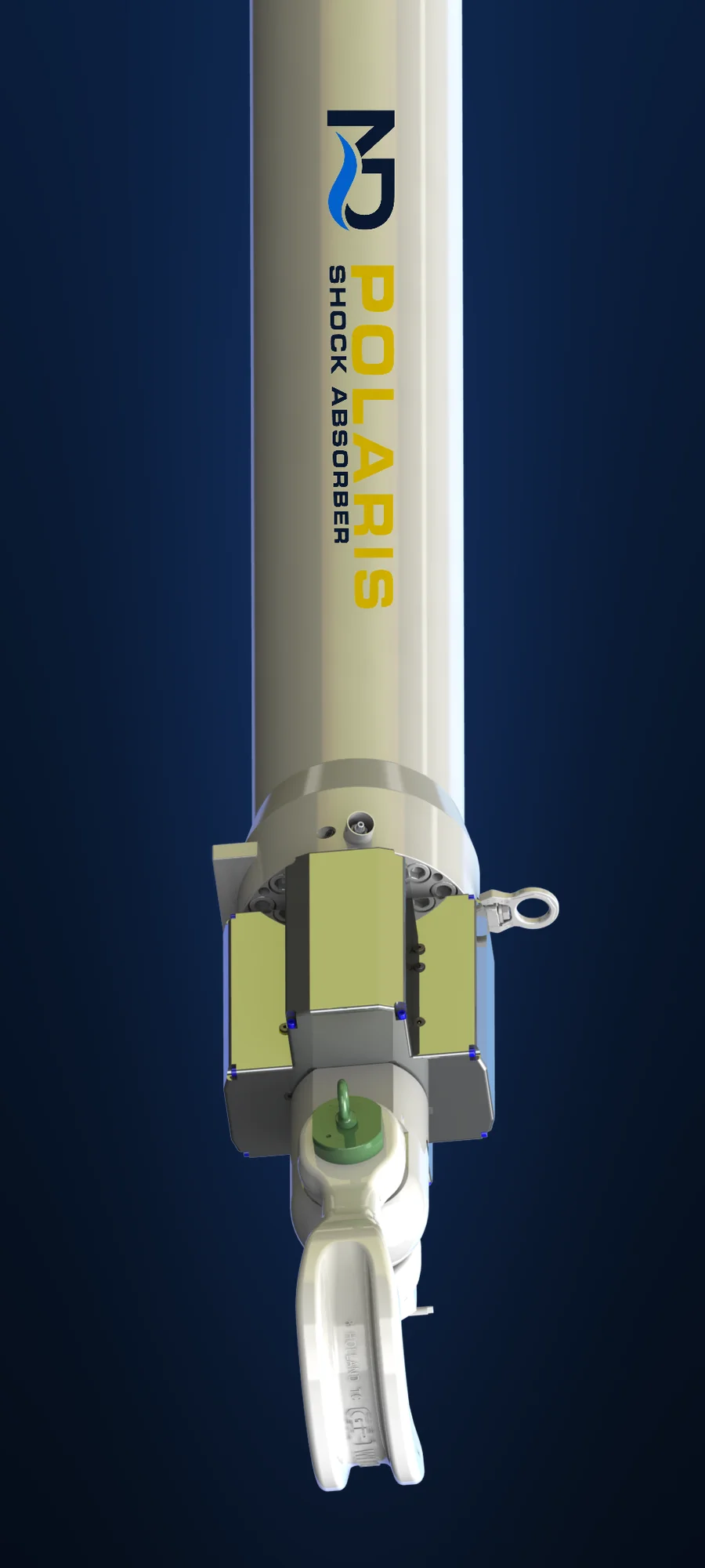 SWL 75–4,000 t · stroke 1.0–8.0 m
| Maximum force (SWL) | 75–4,000 tStandard steps: 75 · 150 · 250 · 400 · 600 · 800 · 1,000 · 1,250 · 1,550 · 2,000 · 2,500 · 3,000 · 3,500 · 4,000 t |
| Stroke length | 1.0–8.0 mStandard steps: 1.0 · 1.5 · 2.0 · 2.5 · 3.0 · 3.5 · 4.0 · 4.5 · 5.0 · 5.5 · 6.0 · 6.5 · 7.0 · 7.5 · 8.0 m |
| Application | Topside overload protection — falling-object loads such as a piling hammer |
| Architecture | Single hydraulic cylinder · internal gas spring · CFD-designed valves — no external accumulators, no needle valves |
| Efficiency | Typically >90% |
| Working principle | Gas spring ramps the force to the damping preset · valve holds the force constant until the payload halts |
| Setup | <1 h typical · fully retracted even with payload attached · ready for reuse without bringing to deck |
| Adjustment | Small quantity of nitrogen · no pilot accumulator filling/draining · no external HPU |
| Rigging | Fitted to the crane hook via slings · connected to the payload via slings |
| Monitoring | Force & stroke measurement · pressure measurement on all volumes · data logging |
| Safety | Fail-safe design · piston rod locking · pull-tested in a frame during manufacture |
| Certification | Designed, classed & tested to DNV-ST-0378 |
| Budget price | Configurations from approximately USD 20,000 |
| Documentation | GA drawing · datasheet · calculation sheet · OrcaFlex model — on request via the form below |
What POLARIS does to a pile-run
A 1500 t pile-run modelled in CONSTELLATION — our in-house time-domain lift simulator — at a 5 m/s run-out: a 1200 t windmill-foundation pile driven by a 300 t hammer. POLARIS takes the punch-through, holding the crane to a low dynamic factor and the force below the unit on a flat valve plateau while it sheds the energy into stroke. It is the same case as the application film further down this page.
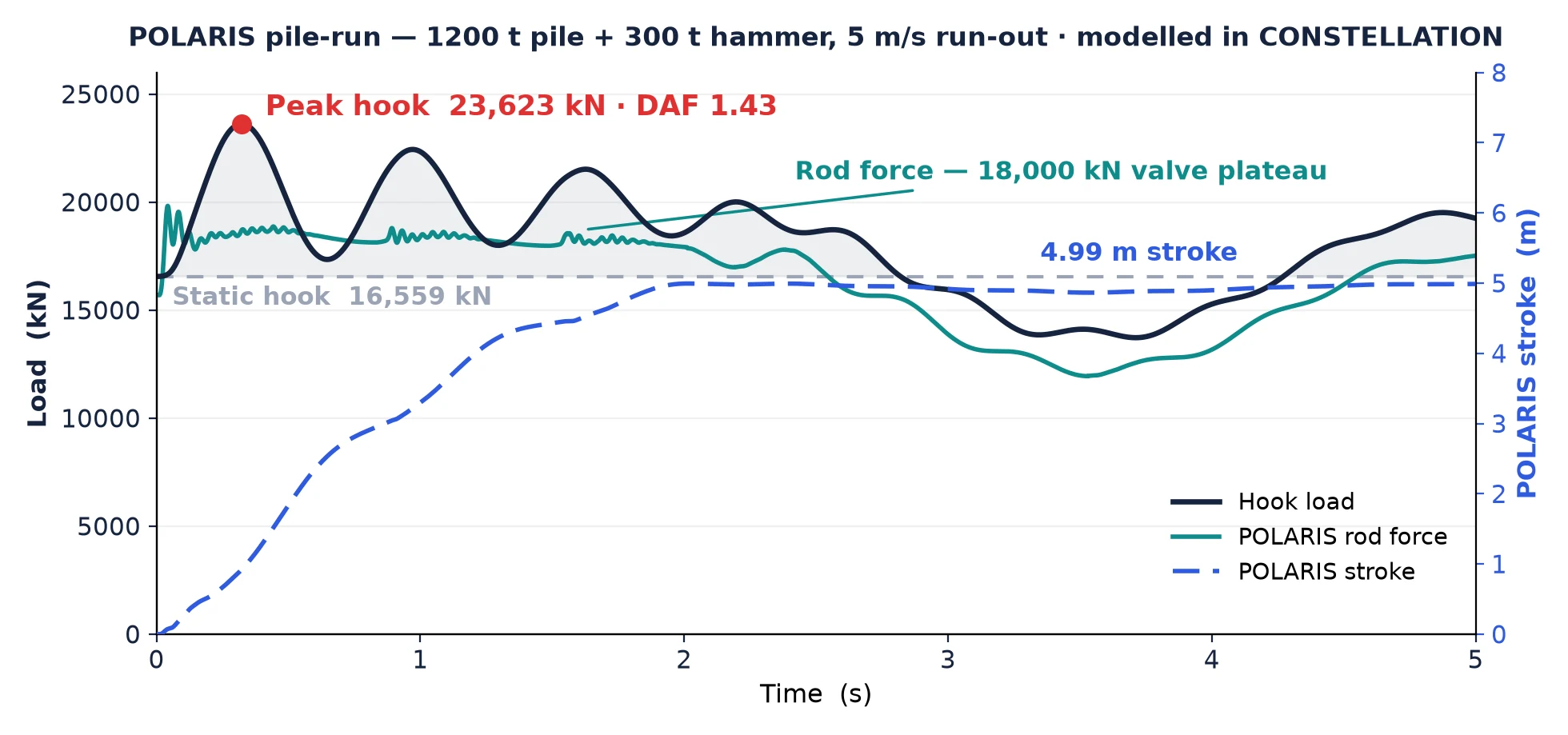
Hook load and rod force through the punch-through, modelled in CONSTELLATION. The 1500 t pile assembly (1200 t pile + 300 t hammer) hangs at a 16,559 kN static hook load. The run snaps the hook to 23,623 kN (DAF 1.43); below the unit the rod force rides the 18,000 kN valve plateau while POLARIS pays out 4.99 m of stroke to arrest the run. The force on the structure peaks at 19,215 kN (payload DAF 1.31).
Engineering prediction for the example pile-run, screened to DNV-RP-N103 practice and our ND-DS basis — not a certified analysis. The rigid-snap figure is an estimate on the crane + sling stiffness, not a simulation result. Confirmed against the project’s own load case before issue.
See how we screen your lift →See POLARIS in action
Rendered frame-for-frame from the CONSTELLATION simulation — the rod stroke you see is the computed stroke channel, and the telemetry is the real result.
Pile-run protection
A 1,500 t pile-and-hammer stack through a 5 m/s run onto POLARIS 2,000 t / 6.0 m — hook held at 23.6 MN (DAF 1.43) against an estimated ~45 MN rigid snap, rod on the 18 MN valve plateau, arrested in 5.0 of 6.0 m stroke, reset in one hour.
One cylinder does it all
Gas spring ramps the force
POLARIS combines a hydraulic cylinder with an internal gas spring. When a falling load — such as a running pile — engages the unit, the gas spring ramps the force up until the damping preset is reached.
The valve holds a flat plateau
A specially designed CFD valve then holds the force constant until the payload comes to a halt, shedding the energy into stroke — no external accumulators, no needle valves, typical efficiency >90%.
Reset and reuse in under an hour
POLARIS is fully retracted even with the payload attached and is ready for reuse in under an hour — no need to bring the unit to deck. Adjustment takes only a small quantity of nitrogen, with no external HPU.
Compact and rugged package
A considered mechanical layout protects key components while making adjustment, handling, upending and maintenance straightforward.
Committed to safety
We follow and exceed the testing requirements in DNV-RP-N202. POLARIS is pull-tested in a frame to ensure structural integrity as part of the manufacturing process. The fail-safe design ensures that even in the event of a system malfunction, the unit maintains a safe state. All pressure volumes are continuously monitored.
Sustainability
POLARIS is designed for repeated use with minimal servicing, extending equipment life and reducing waste. Its compact, all-in-one design eliminates auxiliary components, lowering material usage and environmental footprint.
Engineered for performance
Designed on decades of experience with offshore lifting and shock absorption. Common problems and time-consuming actions are removed.
POLARIS’s lane in the Knowledge Hub
Pile-run protection
Why piles run, what the punch-through does to the crane — and the modelled case.
Read → KB · SYSTEMSShock absorption
Peak-load reduction for falling-object and overload cases — the physics and the hardware.
Read → KB · FUNDAMENTALSDynamic amplification factor
What DAF means, how it is calculated — and what drives it in offshore lifts.
Read →POLARIS, answered
What applications can POLARIS shock absorber be used for?
How does POLARIS shock absorber work?
POLARIS shock absorber is usually fitted to the crane hook via slings and connected to the payload via slings. Read more in our guide to shock absorption.
What are the benefits of POLARIS vs traditional solutions?
- Much lower cost
- Much lower weight
- Much smaller footprint
- Much faster to adjust
- Only a small quantity of nitrogen required for adjustment
- Much higher efficiency
- Easier and much faster filling of gas
- No pilot accumulator filling/draining required, hence no need for an external HPU
- Better filling kit
- Easier to use calculation sheet
When should I choose a traditional solution instead of POLARIS?
Send your lift case.
Lead time and project pricing depends on capacity, stroke and classification — fill in the form and we’ll send drawings, datasheet and a project-specific quotation.