
Pick the wave, press the button, clear the deck — first time.
Quick Lifting
By Peter Wang, COO · December 2025
Practical application: For practical application of this topic, see POLARIS crane shock absorber and engineering studies and analysis.
What is the benefit of quick lifting?
Offshore lifts present several challenges. When using relatively slow cranes, recontact between the payload and deck can occur, as unexpected wave or vessel motions may induce rapid movements that result in impacts. Such collisions can damage equipment and lead to costly delays. The quick lifting ability provided by adaptive PHC and AHC units helps mitigate this risk by reducing the likelihood of payload-deck contact.
How does it work?
The payload is attached to the adaptive PHC or AHC. Tension is kept at say 50% of static weight causing the rod to extend when the crane is lifting. Extension is then done until about 1/3 to 1/2 of compensator stroke is reached. The compensator is now passively keeping tension in the rigging around 50% as the vessel is heaving up and down. At a top of a wave (recommended) the quick lift is activated by the user by the click of a button. The piston rod is the retracted to the fully retracted position in a controlled manner.
The retraction can be done in several ways:
- By switching from a low pressure accumulator to a high pressure accumulator that it pre-charged with oil and gas so that it can fully retract the payload in question.
- Connecting high pressure gas (with a large connection) to the current accumulator so that tension is increased.
- Using AHC HPU to generate required additional lifting force.
What happens in a barge lift-off
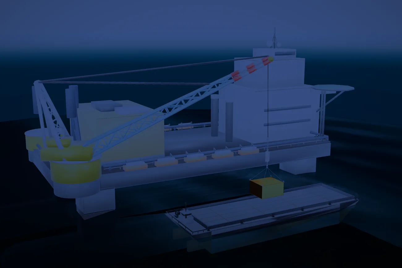
Lifting a heavy load off a transport barge or supply vessel is one of the most exposed moments offshore. Keeping clear of re-contact — the load lifting clear, then a wave bringing the deck back up into it — is the governing safety criterion for a barge lift-off under DNV-RP-N103 §9.5.
A barge lift-off, modelled
A CONSTELLATION Monte-Carlo study: the same 250 t payload taken off a transport barge in Hs 2.16 m / Tp 5.5 s, across 120 modelled sea states per point, lifting at the same favourable moment each time. A conventional crane — rigid line, no compensation, hoisting across the realistic heavy-lift range — against the ANTARES quick-lift snatch:
| Crane hoist speed | Conventional crane — re-contact | ANTARES quick-lift |
|---|---|---|
| 1–3 m/min heaviest lifts (≈1,000–2,000 t) | 100% | 0% |
| 5 m/min | 86% | 0% |
| 10 m/min ≈ the DNV §9.5 hoist floor | 52% | 0% |
| 20 m/min fast, lighter loads | 15% | 0% |
The quick-lift re-contacted in none of the 120 modelled seas at any speed (95% confidence 0–3%). In the modelled snatch the payload leaves the deck at a payload DAF of 1.27 and a peak sling load of 3,118 kN — inside the rigging and crane limits, on 64% of the ANTARES stroke. Modelled in CONSTELLATION as one coupled time-domain load path; deck re-contact evaluated as DNV-RP-N103 §9.5 defines it. One sea state, one case — every lift is sized on its own payload, vessel and sea.
The quick-lift sequence
- Hold light. The payload hangs on the compensator at roughly 50% of static weight — the rod extends as the crane starts lifting.
- Ride the heave. Extension stops at about ⅓ – ½ of stroke; the unit passively keeps the rigging tensioned while the vessel heaves.
- Pick the moment. At a wave top — the recommended trigger point — the operator activates the quick lift with one command.
- Clear first time. The rod retracts fully, fast but controlled — the load is off the deck before the next wave arrives.
| Retraction method | How it works |
|---|---|
| Accumulator switch | Low-pressure to pre-charged high-pressure accumulator — sized to retract the payload in question |
| Gas injection | High-pressure gas connected to the working accumulator through a large connection |
| AHC power unit | The HPU generates the additional lifting force |
Keep the trigger tension moderate — too much invites unnecessary dynamics. End damping protects the unit either way, but not needing it is better practice.
Quick lifting — frequently asked
What is quick lifting?
Why is it needed?
When is the lift triggered?
How is the fast retraction powered?
How likely is deck re-contact without a quick-lift?
Which units can do it?
Working on a lift that needs this?
Fast lifts increase DAF non-linearly — POLARIS keeps you within chart. Send the crane and load case and we'll size it.
See it in action
ANTARES quick lift — “clear first time” off a heaving feeder barge, simulated in CONSTELLATION