
When the sea moves, the hook load climbs above the static weight.
In real crane lifts, DAF is usually caused by relative motion. The crane tip, hook, wire, slings and payload do not all move together. When the system suddenly takes up that motion, the wire and rigging behave like springs and the velocity difference becomes a tension spike.
Supply-vessel deck lift. A cargo container on a supply vessel follows the vessel heave and roll, while the crane tip follows the crane vessel or platform. If the hook is moving up as the deck or container is moving down, the sling can go from slack or low tension to fully loaded in a fraction of a second. This snap load can be much higher than the static container weight.
Splash-zone crossing. During a splash-zone crossing, buoyancy, drag, added mass and wave particle velocity change quickly as the payload passes through the free surface. The hook load can rise and fall rapidly, especially when the crane, wire and payload dynamics line up with the wave period.
Other common triggers include sudden lift-off from deck, landing impact, snagging, fast crane motion, emergency stops and resonance in the crane-wire-payload system.
Snap loads — the worst-case DAF
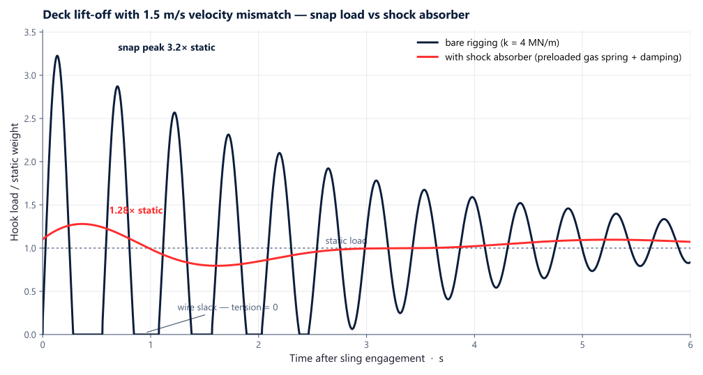
The most violent DAF events are snap loads: the sling goes slack, then re-tensions suddenly. While the wire is slack the hook and payload move independently, and when it comes taut the velocity difference has to be absorbed by wire stretch almost instantly. For a payload of mass m (plus added mass mA if submerged) on rigging of stiffness k, the tension spike above the quasi-static load is approximately
F_{\text{snap}} = v_{\text{rel}} \sqrt{k \, (m + m_A)}where vrel is the relative velocity at the moment the wire re-tensions. Both design handles are visible in the formula: reduce the velocity mismatch (slower crane motion, heave compensation systems, better weather) or reduce the effective stiffness k (a POLARIS crane shock absorber). Stiff rigging is the enemy here — doubling k raises the snap force by 41% for the same velocity mismatch. DNV-RP-N103 sets the criteria for when snap loads must be assessed and how the peak is calculated; the practical mitigation it points to is keeping the wire under tension through the whole wave cycle, which is exactly what a passive heave compensator does.
How to reduce DAF
- Shock absorbers for snap loads. A POLARIS crane shock absorber adds stroke and damping between the crane and payload. It absorbs the kinetic energy of a single shock event — deck lift-off, a snap load, an overload — before it becomes peak crane load. It needs time to reset after an event, so for repeated slack–snap cycles in the wave zone, use heave compensation instead.
- Passive heave compensation for splash-zone crossings. A passive heave compensator reduces relative motion between the crane hook and subsea payload. This keeps rigging tension smoother through the splash zone and reduces the dynamic amplification the crane sees.
- Choose the compensator by operation. RIGEL and CYGNUS cover simpler passive cases, while ANTARES is used for complicated or multi-step subsea lifts with changing buoyancy.
- Control the lift as well as the equipment. Lower crane speed, avoid resonant sea states, plan weather windows and use soft lift-off procedures. The equipment reduces DAF, but the operation still sets the starting conditions.
For product choice, start with the heave compensator selection guide or compare the crane demand in the crane load chart.
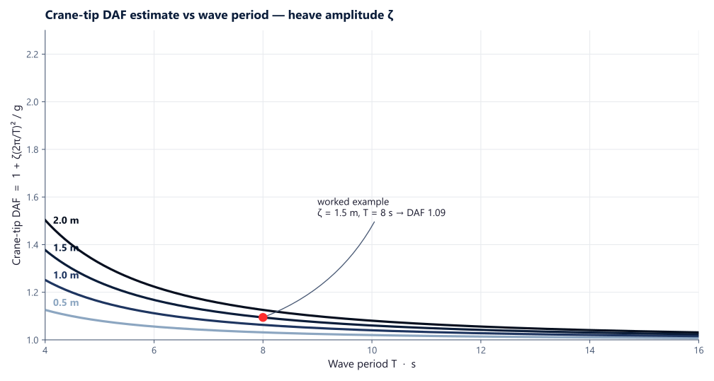
The simplest DAF estimate comes from DNV-OS-H205 (now DNV-ST-N001), which gives:
where aheave is the maximum vertical acceleration at the crane tip and g is gravitational acceleration (9.81 m/s²). For a sinusoidal heave motion with amplitude ζ and period T:
For example, with a 1.5 m heave amplitude and an 8 s period:
This is the crane-tip DAF only — the hook DAF is usually higher because the sling and payload form a spring-mass system that amplifies the crane tip motion, especially near resonance.
More accurate DAF calculations require modelling the full dynamic system: crane boom stiffness, wire rope elasticity, sheave friction, sling arrangement, and payload hydrodynamic properties. Tools like OrcaFlex are commonly used for this.
Typical DAF ranges
| Lift scenario | Uncompensated | With compensation | Primary driver |
|---|---|---|---|
| General offshore lift | 1.2 – 2.5 | 1.05 – 1.3 | crane-tip heave & rigging stiffness |
| Subsea lift | calculated | calculated — the compensator lowers it directly | ST-N001 §16.17 with RP-N103 — no flat minimum; line tensions ≥ 10% of static |
| Snap / lift-off (worst case) | up to ~3.2× (illustrative) | ~1.28× (shock absorber) | slack-then-snap in the wire |
DAF by lift scenario
Offshore, DAF splits into two mitigation regimes — a repeated wave-cycle heave problem, and a single shock or snap event — and each has a different answer.
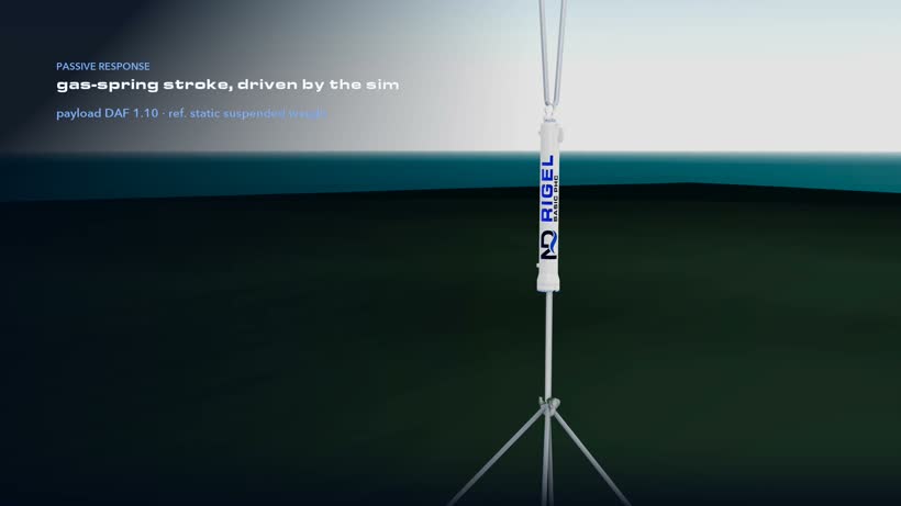
Crossing the water surface
Entering the splash zone, slam, varying buoyancy and snap loads hit almost at once. Passive heave compensation keeps the sling taut and cuts the crane-motion part of the DAF; the water-entry slam itself stays a hydrodynamic (DNV-RP-N103) check.
Drivers: slam · varying buoyancy · crane-tip heave
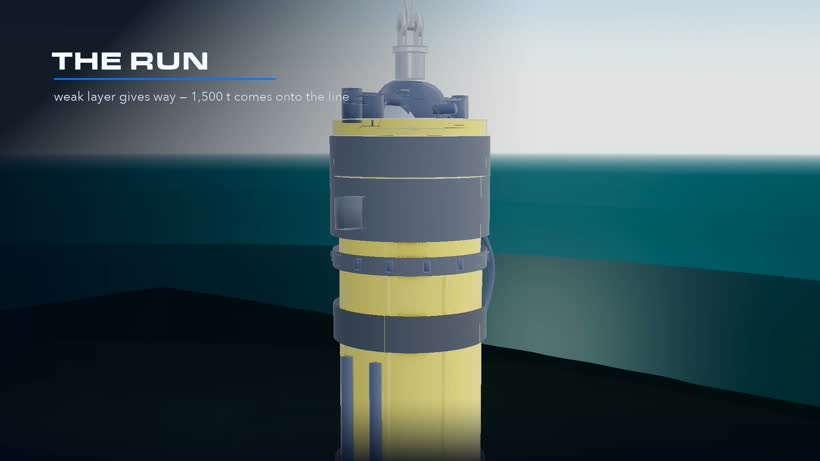
Running a pile or heavy structure
Lowering a long pile or heavy object at speed, a slack-then-snap or shock event at the crane tip drives the peak — a sharp, short-duration spike rather than a wave-cycle heave.
Drivers: snap / shock load · lowering speed · rigging stiffness
See the DAF, before the lift
Real CONSTELLATION runs for the two scenarios — the tension and load traces that show the DAF and how the equipment holds it.
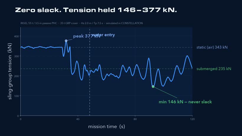
Splash zone · RIGEL. Sling-group tension held through water entry — no slack, no snap. Payload DAF 1.10.
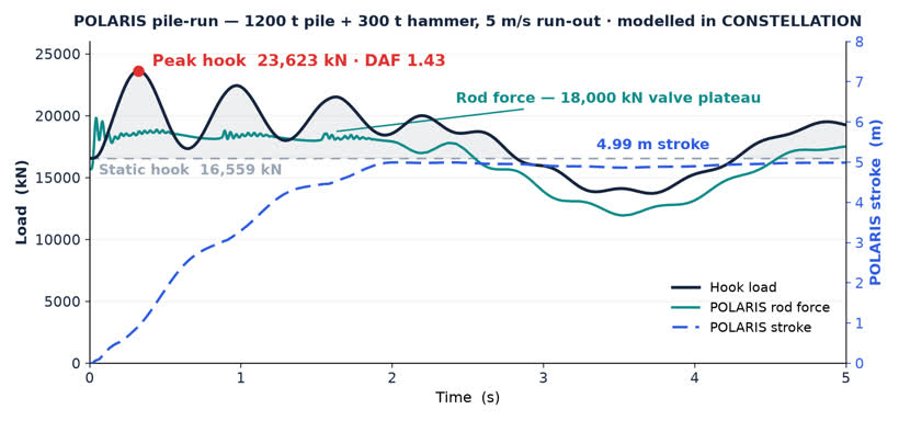
Pile run · POLARIS. Peak crane-tip load with vs without the shock absorber — the spike capped in the run.
Estimate your DAF
Crane-tip heave ζ ≈ 1.0 m; rigging amplification ≈ 3.5×. First-pass hook DAF — it captures crane-tip motion and rigging resonance (the DAF spikes when the wave period meets the rigging’s natural period Tn), but not splash-zone added mass, drag or slamming, so a snap-load peak can be higher still. For the design-basis DAF, commission a CONSTELLATION study.