
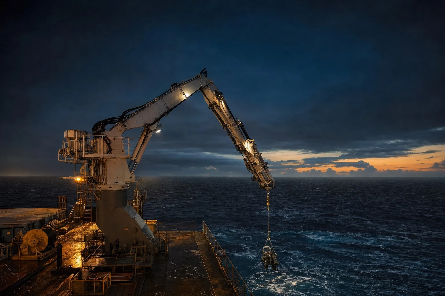
Measure the wave, drive against it — and know what that costs in power.
Active Heave Compensation
By Tord Martinsen, CEO · October 2025
Practical application: For practical application of this topic, see ANTARES Adaptive PHC and engineering studies and analysis.
Active heave compensation (AHC) is a method of reducing the vertical motion of a payload suspended from a crane or winch during offshore operations. Unlike passive heave compensation, which relies on mechanical spring-damper systems, active heave compensation uses powered hydraulic or electric actuators controlled by sensors and algorithms to actively counteract wave-induced motion.
AHC systems are commonly used in subsea construction, pipe laying, ROV deployment, deep-water drilling, and heavy lift operations in challenging sea states.
How does active heave compensation work?
An active heave compensator consists of at least:
- An actuator, which may be a linear (e.g. cylinder) or rotary (e.g. winch) actuator, with position measurement.
- A motion reference unit (MRU), which may be placed on the AHC in case of an inline AHC or on the vessel in case of an integrated AHC.
- Some form of manipulation of the actuator position, that is sufficiently fast to be able to follow vessel motion (e.g. hydraulic motor).
When the active heave compensation mode is turned on the control system keeps the payload stationary when seen from a stationary reference frame, by actively counteracting the wave motion using the actuator.
Active heave compensation can reach efficiencies above 90%. Active heave compensators usually work best for longer wave periods.
The main types of AHC
There are many types of active heave compensators, here are some of the main ones:
- Electric rotary AHC, usually best suited for lighter payloads.
- Hydraulic rotary AHC, for heavy payloads.
- Deck based sheave AHC, for retrofitting.
- Topside inline AHC, for basic AHC tasks topside.
- Subsea inline AHC, combines AHC with many of the properties of an adaptive PHC.
| AHC type | Payload class | Where it fits |
|---|---|---|
| Electric rotary (winch) | Lighter payloads | Fast, clean installations without hydraulics |
| Hydraulic rotary (winch) | Heavy payloads | High-force continuous compensation |
| Deck-based sheave | Existing crane systems | Retrofitting AHC without replacing the winch |
| Topside inline | General | Basic AHC duties above the hook |
| Subsea inline | General / subsea | Active control plus many adaptive-PHC properties in one unit |
The inline architecture is the cost-effective route for most cases — the gas spring carries the load, the actuator only steers it.
Active vs Passive Heave Compensation
| Feature | Active (AHC) | Passive (PHC) |
|---|---|---|
| Energy source | Typically external power (HPU) — ND’s VEGA (in development) runs on battery, no umbilical | Self-contained (gas spring) |
| Accuracy | Very high (>95%) | Good (70-90%) |
| Complexity | High | Low |
| Cost | Higher | Lower |
| Best for | Precise positioning, pipe lay | Splash zone, subsea landings |
For many offshore lifting operations, passive heave compensation provides sufficient performance at lower cost and complexity. Norwegian Dynamics specializes in advanced passive heave compensators that achieve performance levels approaching AHC systems.
How much energy is consumed?
A simple example, 100t is compensated in air for a sinusoidal movement with amplitude 1 m and period 10 s. Assume that the AHC is an inline AHC with the following properties:
- 10:1 gas to oil ratio and 4 m stroke.
- Efficiency of AHC components 90%.
- 50 % energy regeneration.
For an inline AHC the payload is kept at mid position by passive gas pressure. It is brought out from mid position by the hydraulic motor. So our energy consumption will be:
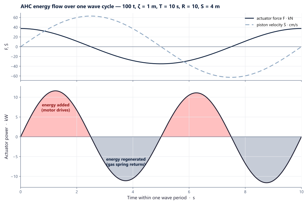
In the first red area we need to add energy to extend the cylinder, then we let the cylinder retract and regenerate energy until we reach mid stroke where we need to add energy to retract further, finally we regenerate energy by letting the cylinder extend to mid position. It can be shown that the force that the AHC system has to provide is:
Since S follows the sinusoidal motion we can rewrite it as:
F = m g \left[ \left( \frac{S_\mathrm{max}(R – 0.5)}{S_\mathrm{max}(R – 0.5) – \zeta\cos{\omega t}} \right)^{\gamma} – 1 \right]Our integral can then be written as:
Due to symmetry we can integrate like this:
W = \int_{0}^{10\,\mathrm{h}}
\left|
m g
\left[
\left(
\frac{S_\mathrm{max}(R – 0.5)}
{S_\mathrm{max}(R – 0.5) – \zeta\cos{(\omega t)}}
\right)^{\gamma}
– 1
\right]
\, \zeta \omega \sin{(\omega t)}
\right|
\, dt
And finally we adjust for the efficiencies and get:
W = \int_{0}^{10\,\mathrm{h}}
\left|
m g
\left[
\left(
\frac{S_{\mathrm{max}}(R – 0.5)}
{S_{\mathrm{max}}(R – 0.5) – \zeta \cos(\omega t)}
\right)^{\gamma}
– 1
\right]
\, \zeta \omega \sin(\omega t)
\right|
\, dt \cdot \frac{(1-\eta_{\mathrm{regen}})}{\eta_{\mathrm{AHC}}}
\
By numerical integration we find that to be 207 MJ or 57 kWh.
So as we can see even for a heavy payload being compensated for a significant amount of time the required battery capacity isn’t super big, comparable to an EV battery.
For more accurate calculations that includes friction, hydraulic losses, more accurate efficiency models for pump/motors/battery, accurate equation of state, etc. please contact Norwegian Dynamics.
The energy budget, in three lines
- The case. 100 t payload compensated in air, sinusoidal ζ = 1 m at T = 10 s; inline AHC with R = 10, S = 4 m; 90% component efficiency, 50% regeneration.
- The physics. The gas spring holds the payload at mid-stroke; the motor only adds energy through half of each cycle and regenerates through the other half — peak actuator power ≈ 12 kW.
- The answer. Ten hours of continuous compensation ≈ 207 MJ = 57 kWh — an EV-battery-class pack. This is why a battery-powered, umbilical-free active unit is feasible.
Numbers from the integration above; friction, hydraulic losses and full pump/motor/battery efficiency models refine them — that full model is part of a CONSTELLATION study.
When to Choose AHC vs PHC
Choose active heave compensation when:
- Very high compensation accuracy is required (>95%)
- The operation involves precise subsea positioning
- Continuous compensation is needed for extended periods
- The vessel already has an HPU available
Choose passive heave compensation when:
- The primary concern is splash zone crossings
- Cost and simplicity are priorities
- The compensator needs to be self-contained
- Shock absorption is the main requirement
→ Not sure which is right? Contact our engineers for a free consultation.
Related Products
- ANTARES Adaptive PHC — Advanced passive heave compensator with multiple operating modes and automatic damping control
- RIGEL Basic PHC — Cost-effective passive heave compensator for straightforward operations
Further Reading
Active heave compensation — frequently asked
What is active heave compensation?
What does an AHC consist of?
How efficient is it?
How much energy does it use?
Active or passive — which do I need?
Working on a lift that needs this?
AHC is rarely the right answer in isolation — it usually pairs with passive damping. Tell us your accuracy, sea state and power constraints and we'll come back with the right architecture.