Passive Heave Compensation Basics
Understand the hardware, then read the response model.
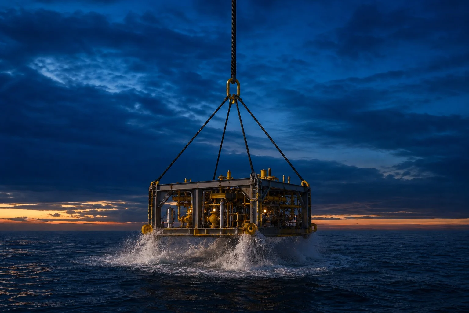
Passive heave compensation (PHC) is a technique used in offshore operations to reduce the vertical motion transferred from a crane hook to a suspended payload. It works without external power by using a gas-spring and hydraulic damper system that absorbs wave-induced motion.
When a vessel moves up and down with the waves, the crane hook follows. Without compensation, the payload experiences the same motion, which creates dangerous dynamic loads during splash zone crossings, subsea landings, and other critical operations. A passive heave compensator acts as a buffer, absorbing much of this motion.
ND’s passive range is built on this physics: RIGEL, CYGNUS and the adaptive ANTARES. Compare their capacity bands, damping control and sizing to DNV-RP-N202. For sensor-controlled compensation, see active heave compensation.
How does a passive heave compensator work?
A PHC has three main parts:
- Working cylinder: vacuum above the piston and oil on the rod side, with the rod down to the load
- Gas accumulator: nitrogen over oil; the compressed gas is the spring that carries the payload
- Damping restriction: in the oil line between the cylinder and the accumulator; oil squeezed through it dissipates the wave energy
Inside the unit: cylinder and gas accumulator
A search for a “heave compensation cylinder” finds half the machine. The working cylinder hangs in tension in the lift wire, but the spring is not inside the cylinder at all. It lives in a separate gas accumulator connected to it:
The unit hangs in the wire, rod down to the load. Above the working piston the cylinder is evacuated. Below the piston, the rod-side chamber is oil-filled and connected through a damping restriction to the accumulator, where nitrogen sits over the oil. When hook and load move apart, the unit extends: rod-side oil is displaced through the restriction into the accumulator, the nitrogen compresses, and wire tension rises. That pressure-volume curve is the gas spring. The restriction is the damping: wave energy leaves the system as heat in the oil squeezed through it.
Family differences sit on the accumulator’s gas side: ANTARES adds a charge valve and gas bottles so the spring can be re-tuned between lift phases; CYGNUS carries a bleed-off valve for datum setting. The geometry above is common to the whole passive family.
Key applications
- Splash zone crossings: reducing dynamic loads as the payload passes through the wave zone
- Subsea landings: controlling the landing speed for precise placement
- Resonance avoidance: preventing amplification of motion at certain wave periods
- Tension management: reducing tension variation in a taut cable or riser within the configured stroke and operating range
- Shock absorption: protecting the payload and crane from impact loads
PHC performance factors
The efficiency of a passive heave compensator depends on four things:
- Stiffness: set by the gas volume; a higher gas-to-oil ratio R and a longer stroke give a softer spring and a longer natural period.
- Damping: the restriction in the oil line, enough to control resonance without stiffening the response.
- Stroke: must cover the relative motion between hook and payload with margin, or the unit tops or bottoms out.
- Payload matching: the gas pre-charge must balance the payload’s weight (submerged weight when subsea), so the unit sits near mid-stroke.
Response model: how much hook motion gets through
Heave is vertical motion; here it is the vertical motion of the crane hook caused by waves. A passive heave compensator can be modelled as a spring-mass-damper system that reduces the wave-induced motion below it. The simplified sketch below shows the scenario.
The hook moves as \zeta \cos(\omega t) and the PHC has stiffness k. The water has density \rho_w; the payload has density \rho, mass m and area A_\perp perpendicular to the heave motion.
Because this example assumes a subsea payload, buoyancy, drag and added mass have to be taken into account. These three effects change the response in different ways (buoyancy shifts the equilibrium load, added mass changes the effective inertia, drag dissipates energy) and each can help or hurt depending on the case and frequency.
Added mass
m_A = \rho_w C_A V_RWhere C_A is the added mass coefficient (can be found in DNV-RP-N103) and V_R is the reference volume.
Drag
F_D = \tfrac{1}{2}\rho_w C_D A_\perp \dot z |\dot z|Where C_D is the drag coefficient and \dot z is the payload vertical velocity.
Buoyancy
F_B = \rho_w V gWhere V is the displaced volume of the payload and g is the acceleration of gravity.
Gas-spring stiffness
For screening, the gas-spring stiffness is taken as a secant value, the force difference from equilibrium stroke to full stroke divided by the stroke change:
k = \frac{p_1 A_0 - p_0 A_0}{\Delta S}Where p_0 is the equilibrium pressure, p_1 the pressure at full stroke, \Delta S = 0.5\,S the stroke from equilibrium to full stroke, and A_0 the effective (rod-side annulus) area of the working piston. A secant value is a screening simplification: the small-motion stiffness at equilibrium differs, so everything built on it below is an equivalent-linear estimate rather than an exact property.
Let us assume the following:
- The full stroke length is S, and we are at mid-stroke during equilibrium.
- The gas is compressed adiabatically: at wave periods it has no time to exchange heat.
- The equilibrium force should be equal to the force of gravity minus buoyancy.
From these assumptions, we then get:
k = \frac{(\rho - \rho_w) \, V \, g}{0.5 \, S}\left[\left( \frac{V_{\mathrm{eq}}}{V_{\mathrm{eq}} - 0.5 \, A_0 \, S} \right)^\gamma - 1\right]\gamma is the gas’s stiffness exponent: 1.4 for an ideal gas, but for nitrogen at a compensator’s charge pressures about 1.6 at 10 MPa, 2.0 at 20 MPa and 2.4 at 30 MPa, because nitrogen is a real gas (see resonance avoidance).
We could further assume that the equilibrium volume can be defined as:
V_{\mathrm{eq}} = (R - 0.5) \, A_0 \, SWhere R is the gas-to-oil ratio, which is set by the case-specific accumulator and cylinder configuration. A larger value of R corresponds to a softer spring.
We then get the following expression for the PHC stiffness k:
k = \frac{2 (\rho - \rho_w) \, V \, g}{S}\left[\left( \frac{R - 0.5}{R - 1} \right)^\gamma - 1\right]Which we can rewrite as:
k = \frac{2 \, m \, g}{S}\left( 1 - \frac{\rho_w}{\rho} \right)\left[\left( \frac{R - 0.5}{R - 1} \right)^\gamma - 1\right]Flow restriction
Fluid flow through a restriction is typically given as:
Q = A_f \, \alpha \, \sqrt{\frac{2 \, \Delta p}{\rho_{\text{oil}}}}Where:
- Q is the fluid volumetric flow,
- A_f is the smallest flow area,
- \alpha is the discharge coefficient, and
- \Delta p is the pressure loss.
Using this as a basis, we can find the force due to hydraulic restriction:
F_h = A_0 \, \Delta p = A_0 \, \frac{\rho_{\text{oil}}}{2}\left( \frac{A_0 \, \dot{S}}{A_f \, \alpha} \right)^2Also note that the sign of the hydraulic force will depend on extension or retraction of the rod.
Further, it may have a different magnitude if check valves are present.
The hard part is \alpha. It depends on many variables and is hard to calculate, so it comes from CFD or measurement.
Seal friction
Seal friction is hard to model. It depends on many factors, including:
- Pressure of fluid
- Pretension of elastic element
- Seal material
- Speed of piston or piston rod
- Surface roughness
- Fluid type
- Width of seal
- Seal configuration
A full seal-friction model is beyond the scope of this introduction; the practical point is that friction varies with every factor above.
Equation of motion
Now let us use the above with the following assumptions:
- Seal friction is ignored (in reality it can be significant).
- Hydraulic restriction is ignored here to keep the model illustrative: in the real unit that restriction is the designed damping, and it is exactly what caps the resonant peak and controls the landing response.
- Drag is ignored (reasonable when the PHC isolates well, because the payload then moves slowly through the water).
- Ignore stiffness and damping of rigging/wire rope.
- Ignore hydrodynamics of PHC.
- Ignore self weight of PHC.
A more accurate numerical solution with everything included (and a more precise equation of state for the gas pressure) is available from Norwegian Dynamics.
We can apply Newton’s second law to the payload mass to find out how it moves relative to the crane hook.
Let us assume that downwards is the positive direction:
This has a steady-state solution given as:
z(t) = \frac{k \, \zeta}{(m + m_A)\, \omega^2 - k} \, \cos(\omega t)What we want to know is the ratio between the payload motion and the hook motion.
\frac{z(t)}{\zeta \, \cos(\omega t)} = \frac{k}{(m + m_A)\, \omega^2 - k}We can then change \omega to \frac{2 \pi}{T_p}, where T_p is the wave period, and replace k with our expression above:
\begin{aligned}\frac{z(t)}{\zeta\cos\left(\frac{2\pi t}{T_p}\right)} &= \frac{1}{\lambda-1}, \qquad \lambda = \left(\frac{T_n}{T_p}\right)^2 \\ \lambda &= \underbrace{\frac{m+m_A}{m}}_{\text{Added mass}}\;\underbrace{\frac{\rho}{\rho-\rho_w}}_{\text{Buoyancy}} \\ &\quad\times\underbrace{\frac{2\pi^2}{g\,T_p^2}}_{\text{Wave period}}\;\underbrace{\frac{S}{\left[\left(\frac{R-0.5}{R-1}\right)^{\gamma}-1\right]}}_{\text{PHC}}\end{aligned}Based on this ratio we can define the passive heave compensation efficiency. If the ratio is 0 the payload does not move at all; below 1 the compensator is isolating the payload; above 1 the motion is amplified. Resonance is the specific condition where the undamped model’s denominator goes to zero; amplification near that period is the warning sign. The calculator below evaluates that undamped, single-frequency screening expression with the secant stiffness above. It is prefilled with the worked example’s values; replace them with your case. It cannot size a unit: damping, drag, irregular seas, stroke and pressure limits, landing speed and structural loads sit outside this model, and come from a lift screen in CONSTELLATION.
Passive heave compensation efficiency calculator
Fixed screening constants: seawater density ρw = 1,030 kg/m³ and g = 9.81 m/s². The gas exponent γ is nitrogen’s real stiffness exponent at the charge pressure you choose; an ideal gas would give 1.4.
We can also define the natural period of the PHC as:
T_n = \pi \sqrt{\frac{m + m_A}{m} \,\frac{\rho}{\rho - \rho_w} \,\frac{2S}{\,g\!\left(\left(\dfrac{R - 0.5}{R - 1}\right)^{\!\gamma} - 1\right)}}Worked example: reading the motion ratio
Take the case the calculator is prefilled with: a 100 t steel payload (ρ = 7,850 kg/m³) with 20 t added mass, on a PHC with 6 m stroke and gas-to-oil ratio R = 16, in waves of period Tp = 8 s, with the nitrogen charged to about 20 MPa (γ = 1.97, its real stiffness exponent there):
- Spring softness. The gas-spring bracket \left(\frac{R-0.5}{R-1}\right)^{\gamma}-1 \approx 0.067. A high R and a long stroke make a soft spring.
- Natural period. T_n \approx 16\ \text{s}, well above the 8 s waves, so the system operates in its isolation range.
- Motion ratio. The expression above gives ≈ 0.34: the payload sees about a third of the hook motion, so roughly two-thirds of the wave-induced motion is removed.
- Gas exponent. With the ideal-gas 1.4 in place of nitrogen’s real exponent, R = 12 would seem to give the same 16 s. At the real exponent it gives 13.5 s, and the payload keeps about half the hook motion (0.54, not 0.33).
The closed-form model is undamped and conservative near resonance: real damping caps the peak and adds some transmission in the isolation range. For sizing, the full numerical solution (gas state, damping, drag, rigging) is what a CONSTELLATION study runs.
Damping: what kind, and how much
The gas spring stores the energy: the damper decides where it goes. Undamped, the compensator is a spring-mass system that would ring at its natural period after every disturbance. As the piston strokes, oil is forced through orifices or control valves and the flow resistance converts kinetic energy to heat: a force that grows with velocity, capping resonance, settling transients and giving descent-speed control for landing.
| Damping type | Characteristic | Where you meet it |
|---|---|---|
| Linear | F \propto v | Simple to model: rare in real hardware |
| Quadratic | F \propto v^2 | The natural behaviour of orifice flow: strong at speed, gentle when slow |
| Variable | Adjustable orifices / proportional valves | Damping changed per operational phase: the adaptive route |
Variable damping in practice: ANTARES adjusts its level automatically between lift phases; RIGEL and CYGNUS are set manually on deck.
Other subsea uses
Passive heave compensation units can also give other benefits for subsea installations:
- Ability to maintain wire tension throughout the landing phase, which prevents sudden vessel heeling.
- Mitigation of peak loads in the event of re-lifting of the payload.
- Provide tensioning during subsea retrieval to prevent overloading when fixed to seabed.
Choosing the right PHC
Norwegian Dynamics makes three passive lines: RIGEL, the basic unit; CYGNUS, with the widest capacity band, up to 10,000 t for the heaviest and deepest lifts; and ANTARES, the adaptive passive unit with automatic damping control.
→ Need help selecting? See our heave compensator selection guide or contact our engineers.
RIGEL, ANTARES or CYGNUS: at a glance
 |  |  | |
|---|---|---|---|
| Type | Passive | Adaptive passive | Passive |
| Damping | Manual, set on deck | Automatic damping control | Manual, set on deck |
| SWL range | 55 – 1,000 t | 30 – 4,000 t | 12.5 – 10,000 t |
| Stroke | 1.0 – 6.0 m | 2.5 – 8.0 m | 1.0 – 6.0 m |
| Power | None | Battery: no umbilical | Battery: no umbilical |
| Stands out | Simplest, lightest unit | Quick-lift ability | Heavy / deepwater capacity band |
| Certification | Designed & classed · DNV-ST-0378 (Type Approval in progress) | Designed & classed · DNV-ST-0378 | Designed & classed · DNV-ST-0378 |
| Best for | Straightforward splash-zone crossings and basic compensation | Demanding multi-phase lifts needing automatic damping | Heavy and deepwater subsea lifts |
First-pass guidance: the passive vs active heave compensation guide walks the choice question by question.
Passive heave compensation: frequently asked
What is passive heave compensation?
What are the main components of a passive heave compensator?
How efficient is passive heave compensation?
When is a passive compensator the right choice over active?
Which Norwegian Dynamics compensator fits which lift?
Selecting a passive compensator for your next lift?
We size PHCs against the operating range: Hs, Tp, payload, water depth. Send the case and we'll come back with a recommended product.