
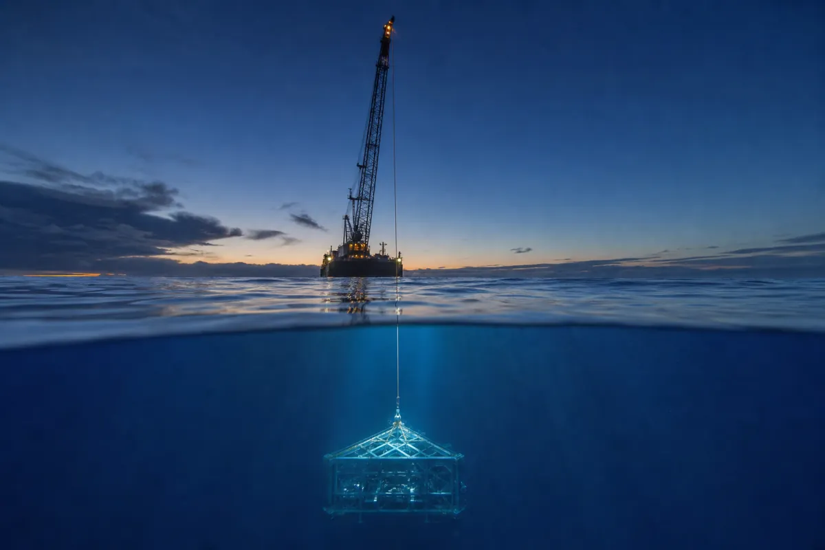
Unter Wasser hebt das Wasser mit Ihnen — und gegen Sie: Auftrieb, Slamming, Widerstand, Zusatzmasse.
Subsea-Hübe
Von Peter Wang, COO · Dezember 2025
Praktische Anwendung: Zur praktischen Anwendung dieses Themas siehe RIGEL Basis-PHC und Ingenieurstudien und Analysen.
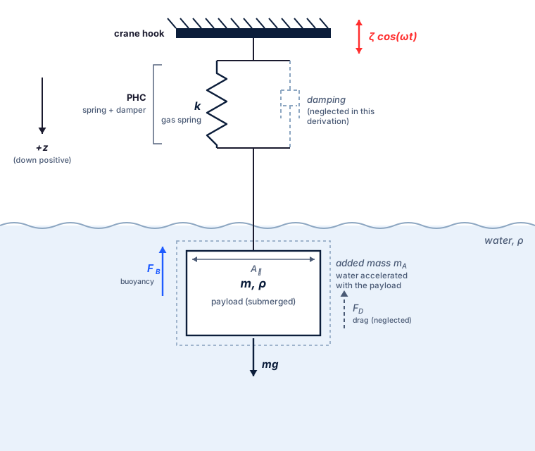
Subsea-Hübe gehören zu den komplexesten Offshore-Einsätzen und erfordern eine sorgfältige Planung, um die hydrodynamischen Kräfte auf die sich im Wasser bewegende Nutzlast zu berücksichtigen. Die beiden wichtigsten Effekte sind Widerstand und Zusatzmasse; beide erhöhen das effektive Gewicht und die dynamischen Lasten auf Kran und Hebeausrüstung.
Das Verständnis dieser Kräfte ist entscheidend für die Auswahl des richtigen Subsea-Seegangskompensators und dafür, dass der Kran über ausreichende Kapazität für den Einsatz verfügt.
Wie beeinflusst Widerstand einen Subsea-Hub?
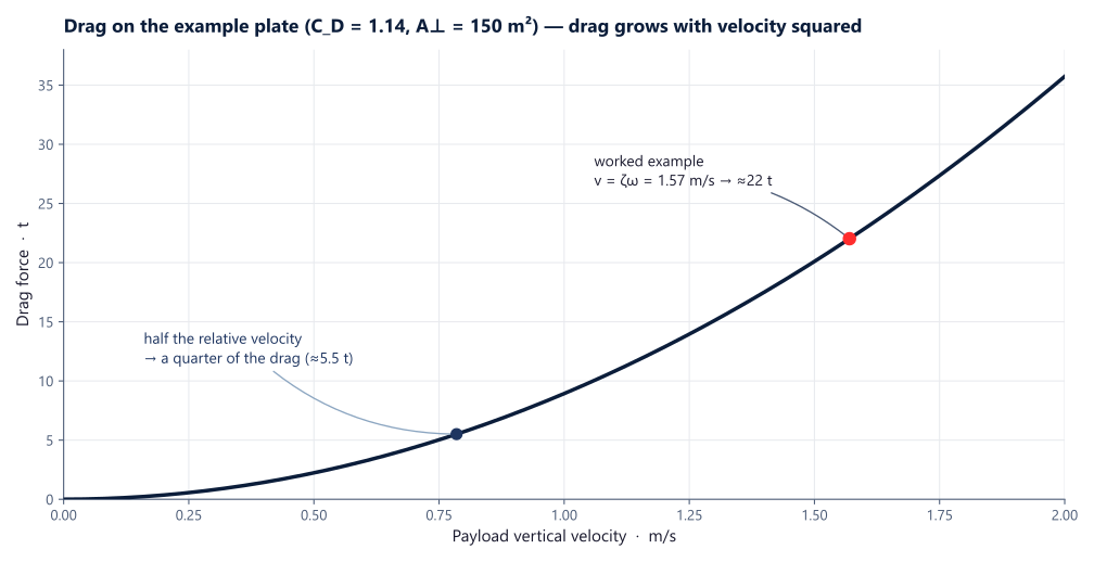
Der Widerstand bei einem Subsea-Hub ähnelt dem Luftwiderstand eines Autos und variiert mit dem Quadrat der Geschwindigkeit. Die Größe der Widerstandskraft hängt von der senkrecht zur Bewegung stehenden Fläche sowie vom Widerstandsbeiwert ab (den wir auch von Autos kennen, die zur Reichweitenerhöhung immer geringere Widerstandsbeiwerte anstreben). Der Hauptunterschied zum Auto besteht jedoch darin, dass das Medium Wasser und nicht Luft ist; Wasser hat eine 1000-mal höhere Massendichte, die ebenfalls in die Widerstandskraft eingeht.
F_D = \tfrac{1}{2}\rho_w C_D A_\perp \dot z |\dot z|
Dabei ist C_D der Widerstandsbeiwert (weitere Informationen finden sich in DNV RP-N103; einige Beispiele sind unten aufgeführt) und \dot z die vertikale Geschwindigkeit der Nutzlast.
| Form | C_D | A_{\perp} | Hinweise |
|---|---|---|---|
| Kugel | C_D = 0.5 | A_{\perp} = \pi r^2 | |
| Horizontaler Zylinder | C_D = 1.2 | A_{\perp} = 2 r L | |
| Vertikaler Zylinder | \frac{L}{2r}=0.5 \Rightarrow C_D=1.1 \frac{L}{2r}=1 \Rightarrow C_D=0.9 \frac{L}{2r}=2 \Rightarrow C_D=0.9 \frac{L}{2r}=4 \Rightarrow C_D=0.9 \frac{L}{2r}=8 \Rightarrow C_D=1.0 | A_{\perp} = \pi r^2 | |
| Würfel | C_D = 1.05 | A_{\perp} = a^2 | Fläche senkrecht zur Strömung. |
| Kegel | C_D = 0.50 | A_{\perp} = \pi r^2 | Spitze in Strömungsrichtung; abhängig vom Kegelwinkel. |
| Rechteckige Platte | C_D = 1.1+0.02 (\frac{L}{W}+\frac{W}{L}) | A_{\perp} = L W | Senkrecht zur Strömung. |
Betrachten wir ein Rechenbeispiel, um die Relevanz einzuordnen. Angenommen, Sie heben eine Nutzlast in Form einer rechteckigen Platte mit 15 m Länge und 10 m Breite. Die Wellenperiode beträgt 8 Sekunden und die Wellenhöhe 4 m; nehmen Sie sinusförmige Wellen an. Wie groß wird die Kraft sein?
Zunächst bestimmen wir die Spitzengeschwindigkeit; die Wellenbewegung ist gegeben durch
z = \zeta \cos(\omega t)Da \omega = \frac{2 \pi}{T_p} gilt, erhalten wir eine Spitzengeschwindigkeit von 1.57 m/s.
Den Widerstandsbeiwert können wir dann wie folgt berechnen:
C_D = 1.1 + 0.02 \left( \frac{15}{10} + \frac{10}{15} \right) = 1.14
Unsere Widerstandsfläche beträgt:
A_\perp = 10 \cdot 15 = 150 \,\mathrm{m^2}
Wie beeinflusst Zusatzmasse einen Subsea-Hub?
Die Zusatzmasse bei einem Subsea-Hub ist sehr wichtig, da sie große zusätzliche Trägheit und damit große dynamische Kräfte verursachen kann. Sie entsteht dadurch, dass eine Nutzlast bei einer durch Hubbewegung verursachten Schwingung im Wasser auch das umgebende Wasser beschleunigen muss; mathematisch wird sie angegeben als:
m_A = \rho_w C_A V_R
Dabei ist C_A der Zusatzmassenbeiwert (in DNV RP-N103 zu finden; einige Beispiele unten) und V_R das Referenzvolumen.
| Form | C_A | V_R | Hinweise |
|---|---|---|---|
| Kugel | C_A = 0.5 | V_R = \frac{4}{3}\pi r^3 | In allen Richtungen konstant. |
| Zylinder | \frac{L}{2r}=1.25 \Rightarrow C_A=0.62 \frac{L}{2r}=2.5 \Rightarrow C_A=0.78 \frac{L}{2r}=5 \Rightarrow C_A=0.90 \frac{L}{2r}=9 \Rightarrow C_A=0.96 \frac{L}{2r}=\infty \Rightarrow C_A=1.00 | V_R = \pi r^2 L |
Vertikale Bewegung entlang der Zylinderachse in unendlicher Flüssigkeit. |
| Rechteckige Platte |
\frac{L}{W}=1 \Rightarrow C_A=0.58 \frac{L}{W}=2 \Rightarrow C_A=0.76 \frac{L}{W}=4 \Rightarrow C_A=0.87 \frac{L}{W}=8 \Rightarrow C_A=0.93 \frac{L}{W}=\infty \Rightarrow C_A=1.00 | V_R = \frac{\pi}{4}W^2 L | Bewegung senkrecht zur Oberfläche. |
| Kreisscheibe | C_A = \frac{2}{\pi} | V_R = \frac{4\pi}{3} r^3 | Bewegung senkrecht zur Oberfläche. |
| Quadratisches Prisma |
\frac{L}{W}=1 \Rightarrow C_A=0.68 \frac{L}{W}=2 \Rightarrow C_A=0.36 \frac{L}{W}=4 \Rightarrow C_A=0.19 \frac{L}{W}=10 \Rightarrow C_A=0.08 | V_R = W^2 L | Prismatischer Körper mit quadratischer Grundfläche. |
Betrachten wir ein weiteres Rechenbeispiel. Angenommen, Sie heben eine Nutzlast in Form einer rechteckigen Platte mit 20 m Länge und 10 m Breite. Die Wellenperiode beträgt 8 Sekunden und die Wellenhöhe 4 m; nehmen Sie sinusförmige Wellen an. Wie groß wird die Kraft durch Zusatzmasse sein?
Wir müssen die maximale Beschleunigung bestimmen (die Ableitung der Geschwindigkeit, wie im Widerstandsbeispiel gezeigt); sie ist gegeben durch:
Die maximale Beschleunigung beträgt somit:
Als Nächstes beträgt der Zusatzmassenbeiwert 0.36 und unser Referenzvolumen 2000 Kubikmeter. Damit können wir die Kraft wie folgt berechnen:
F=m a=1025 \cdot 0.36 \cdot 2000 \cdot 1.23=98 \mathrm{t}Beachten Sie, dass die Zusatzmasse bei Subsea-Hüben nahe dem Meeresboden durch Einengung zunehmen kann.
Vom Deck zum Meeresboden, ein Durchgang
Ein durchgehendes Absenken: Der Kompensator wird an Deck verriegelt, direkt über der Oberfläche entriegelt und schaltet beim Eintauchen der Last den Gasmodus um — steif beim Wassereintritt, weich für ein nachgiebiges Aufsetzen.
ANTARES adaptiv-passive Seegangskompensation, vom Deck zum Meeresboden — simuliert in CONSTELLATION. Für das vollständige Betriebsfenster-Screening nach Hs×Tp eines solchen Hubs siehe Operabilitäts-Screening.
Die vier Kräfte, eine Tabelle
Widerstand und Zusatzmasse sind die beiden oben berechneten Kräfte — Auftrieb und Slamming vervollständigen das Bild, und jede Phase des Hubs wird von einer anderen Kraft bestimmt:
| Kraft | Skaliert mit | Wann sie dominiert | Auswirkung auf den Hub |
|---|---|---|---|
| Auftrieb | Verdrängtes Volumen (ρwVg) | Ab Wassereintritt; ändert sich beim Durchqueren der Oberfläche schnell | Das effektive Gewicht sinkt und schwankt — Risiko eines schlaffen Seils |
| Slamming | Aufprallgeschwindigkeit beim Wassereintritt | Spritzwasserzone | Kurze, scharfe Lastspitzen auf Nutzlast und Anschlagmittel |
| Widerstand | Geschwindigkeit im Quadrat (½ρwCDA⊥v²) | Eingetauchtes Absenken durch Wellen und Strömung | ≈ 22 t an der Beispielplatte bei Spitzen-Hubbewegungsgeschwindigkeit |
| Zusatzmasse | Beschleunigung (ρwCAVR × a) | Jede Schwingung; nimmt nahe dem Meeresboden zu (Einengung) | ≈ 98 t zusätzliche Trägheitskraft im obigen Beispiel |
In der Spritzwasserzone überlagern sich Slamming, schnell wechselnder Auftrieb und Wellenteilchengeschwindigkeit auf wenigen Metern Wegstrecke — siehe Spritzwasserzonen-Durchquerung und die Methodenreferenz DNV-RP-N103.
Kräfte dieser Größenordnung — eine ≈98 t Trägheitskraft zusätzlich zum statischen Gewicht — erklären, warum schwere Subsea-Hübe mit einem für den Fall ausgelegten passiven Kompensator durchgeführt werden. Er verringert Relativgeschwindigkeit und Beschleunigung (und damit den Widerstand v² sowie die Zusatzmassenkraft) und hält das Seil gespannt, sodass sich schlaffes Seil und Snap Load nicht entwickeln können. Für schwere Hübe und Tiefwasser ist dieser Kompensator CYGNUS (12.5–10 000 t); RIGEL und ANTARES decken die Standard- und adaptiven Fälle ab.
Aufsetzgeschwindigkeit: der letzte halbe Meter
Der Aufprall beim Aufsetzen skaliert mit der Geschwindigkeit — und ohne Kompensation wird diese Geschwindigkeit durch die Hubbewegung des Schiffes bestimmt, die niemand kontrolliert. Ein hartes oder federndes Aufsetzen birgt folgende Risiken:
Ein kompensiertes Aufsetzen beseitigt die Hubbewegungskomponente (die Last sinkt mit der Windenrate ab, nicht mit Windenrate plus Hubbewegung) und erhöht die Dämpfung für die Endannäherung, sodass das Aufsetzen zu einer kontrollierten Verzögerung wird — typischerweise 0.1–0.5 m/s, vom Bediener eingestellt und weitgehend unabhängig vom Seegang:
Einstellbare Dämpfung ist die Schlüsselfunktion für Aufsetzarbeiten: ANTARES ergänzt eine adaptive Gasfeder und Kolbenstangenverriegelung, um die Last nach dem Absetzen sicher zu halten; wenn eine genaue Absenkgeschwindigkeit eingestellt werden muss, bietet ein aktives System diese Regelung. Die Physik des Bewegungsverhältnisses hinter sanften Aufsetzungen wird in Grundlagen der passiven Seegangskompensation hergeleitet.
Wie sich die Tiefe auf den Kompensator auswirkt
Die vier oben genannten Kräfte wirken auf die Nutzlast. Drei weitere Effekte wirken beim Absenken auf den Kompensator selbst — jeder verschiebt das Gerät von seinem Arbeitspunkt — und ein vierter wird durch ingenieurtechnische Disziplin ausgeschlossen:
| Effekt | Auswirkung auf den Kompensator | Die Lösung |
|---|---|---|
| Auftrieb | Das Nettogewicht der Nutzlast sinkt im Wasser → die Gleichgewichtslage wandert einwärts, im schlimmsten Fall bis zum vollständigen Einfahren | Adaptiv: Gasdruck senken, Gleichgewichtslage neu zentrieren — mit einer längeren Eigenperiode als Zusatznutzen |
| Temperatur | ≈ 1% Gasdruck pro 3 °C Abkühlung — etwa 5% des Hubs — gehen beim schnellen Durchqueren der Thermokline verloren | Adaptiv: Bord-Hochdruckgas füllt ihn wieder auf |
| Wasserdruck | ≈ 1 bar pro 10 m Tiefe wirkt auf die Kolbenstangenfläche und drückt die Kolbenstange ein — bei einem 250 t Hub mit einer 180 mm Kolbenstange in 1,000 m ergeben sich ≈ 26 t, wodurch sich die Gleichgewichtslage von der Hubmitte auf ≈⅙ des Hubs verschiebt | Adaptiv: Druck wird mit zunehmender Tiefe abgesenkt |
| Leckage | Wassereintritt — historisch von Leistungsverlusten über Korrosion bis zu Explosionen | Konstruktion + Prüfung + Wartung: doppelte Dichtungen, Außendruckprüfung bei FAT, Kompartimentierung, planmäßiger Dichtungswechsel |
Die ersten drei sind Gleichgewichtsprobleme, die ein adaptives Gerät laufend korrigiert; das vierte wird durch ingenieurtechnische Disziplin beherrscht.
Wie stark wirkt sich die Temperatur aus?
Wie wirkt sich der Tiefendruck auf den Kompensator aus?
Wie wird das Eindringen von Wasser in den Kompensator verhindert?
Warum einen adaptiven Kompensator für große Wassertiefen wählen?
Subsea-Heben — häufige Fragen
Warum ist ein Subsea-Hub schwieriger als ein Hub in Luft?
Wie groß kann der Widerstand werden?
Was ist Zusatzmasse in der Praxis?
Welche Kraft dominiert in der Spritzwasserzone?
Wie schützt Seegangskompensation den Hub?
Arbeiten Sie an einem Hub, der dies benötigt?
Wir legen Kompensatoren für Widerstand, Zusatzmasse und schlagartige Lastspitzen aus – senden Sie den Subsea-Hubfall für eine Produktempfehlung und Dimensionierung (bei schweren Hüben typischerweise den passiven Seegangskompensator CYGNUS).